
 Linear guides
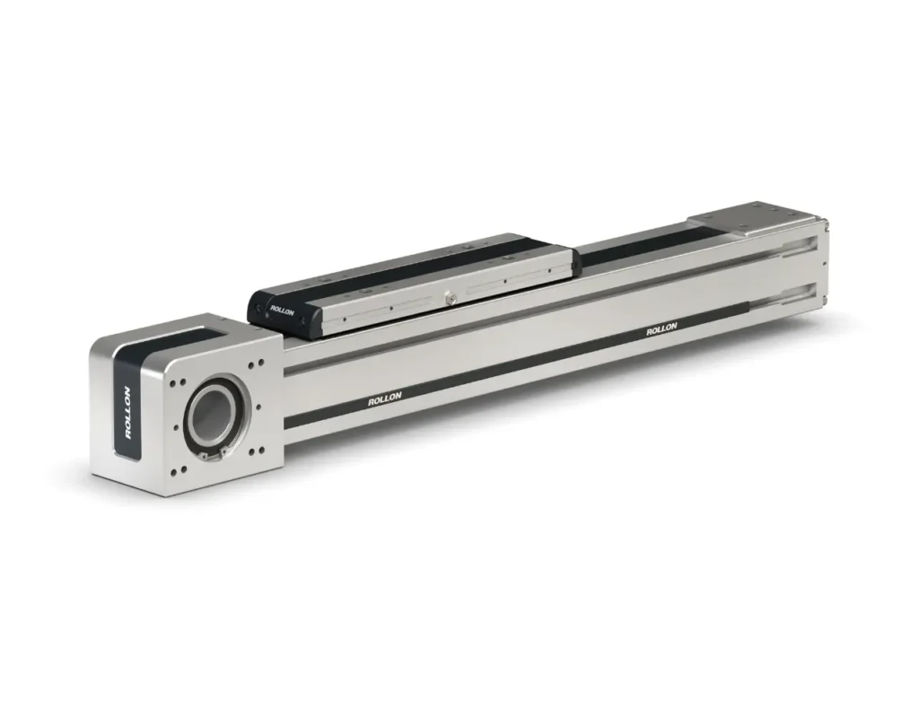 Linear actuators
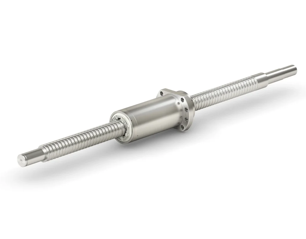 XP Xtrem Position
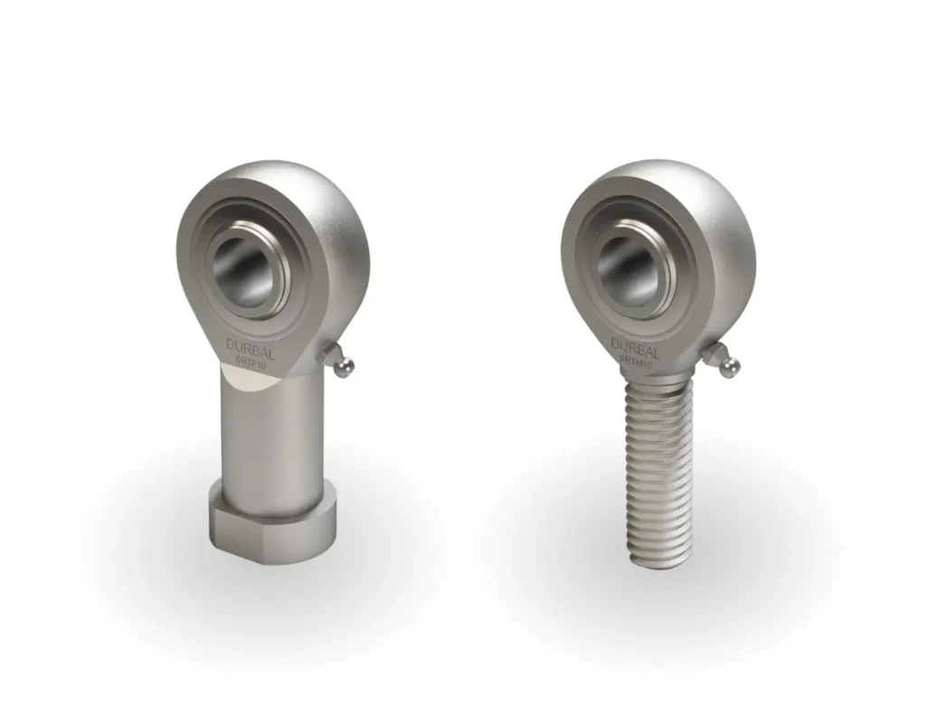 Rod ends
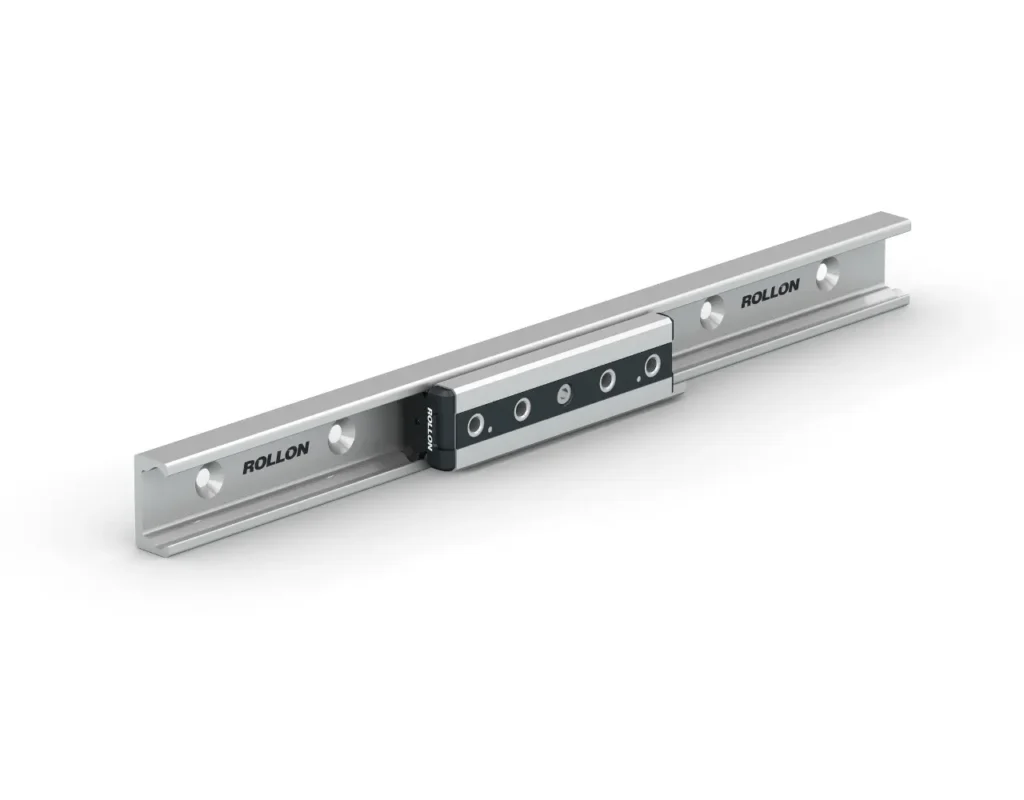
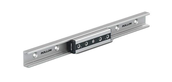
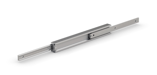
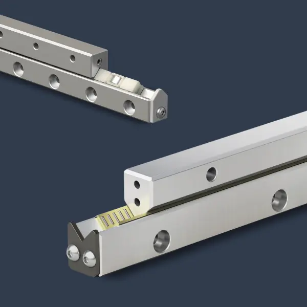
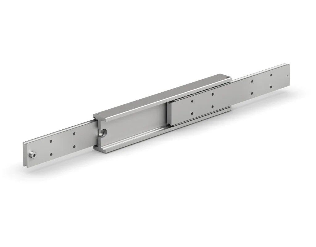 Telescopic rails
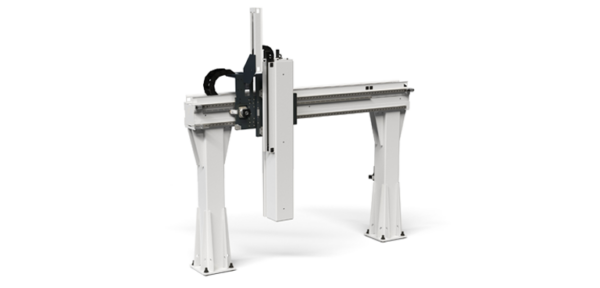
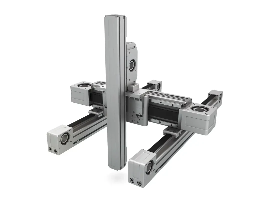 Multi-axis
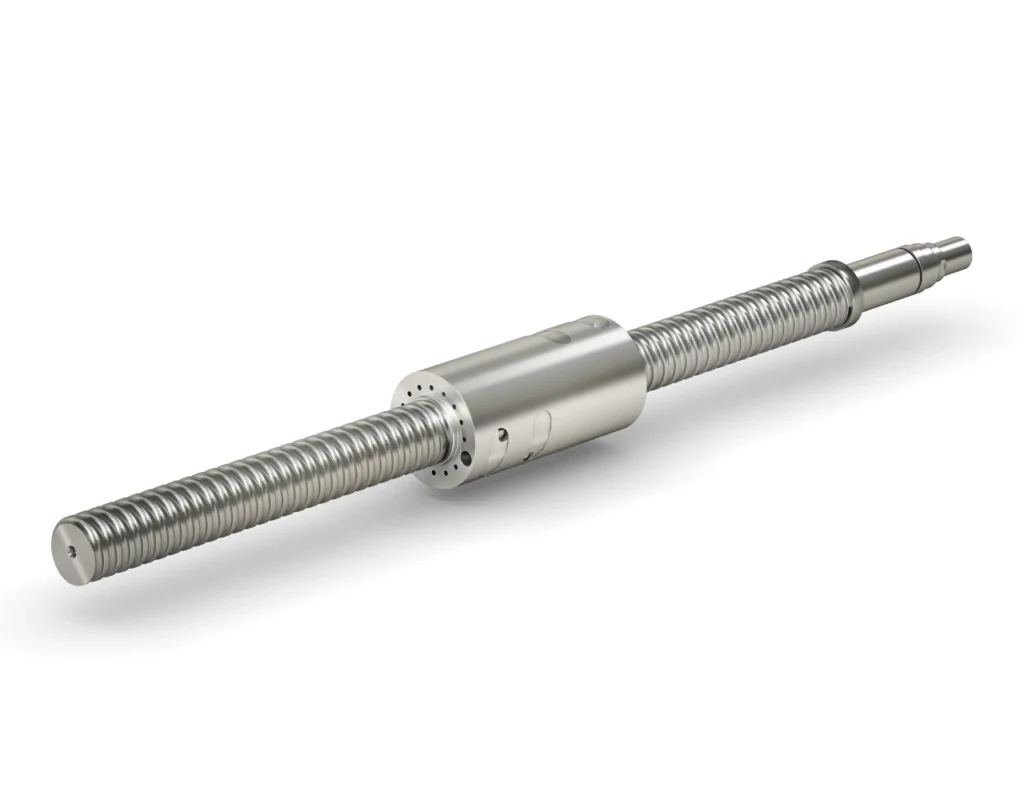 XL Xtrem Load
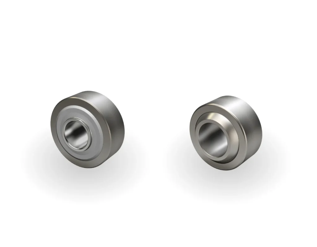 Spherical plain bearings
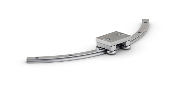
 Curved guides
 Needle roller bearings
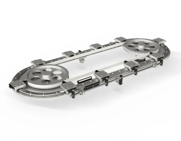
 Circular systems
 Rollon RB
 Locknuts and rings
 Aerospace
 Contract & Building
 Electronics
 Food & Beverage
 Industrial machinery
 Healthcare
 Machine tool
 Material handling
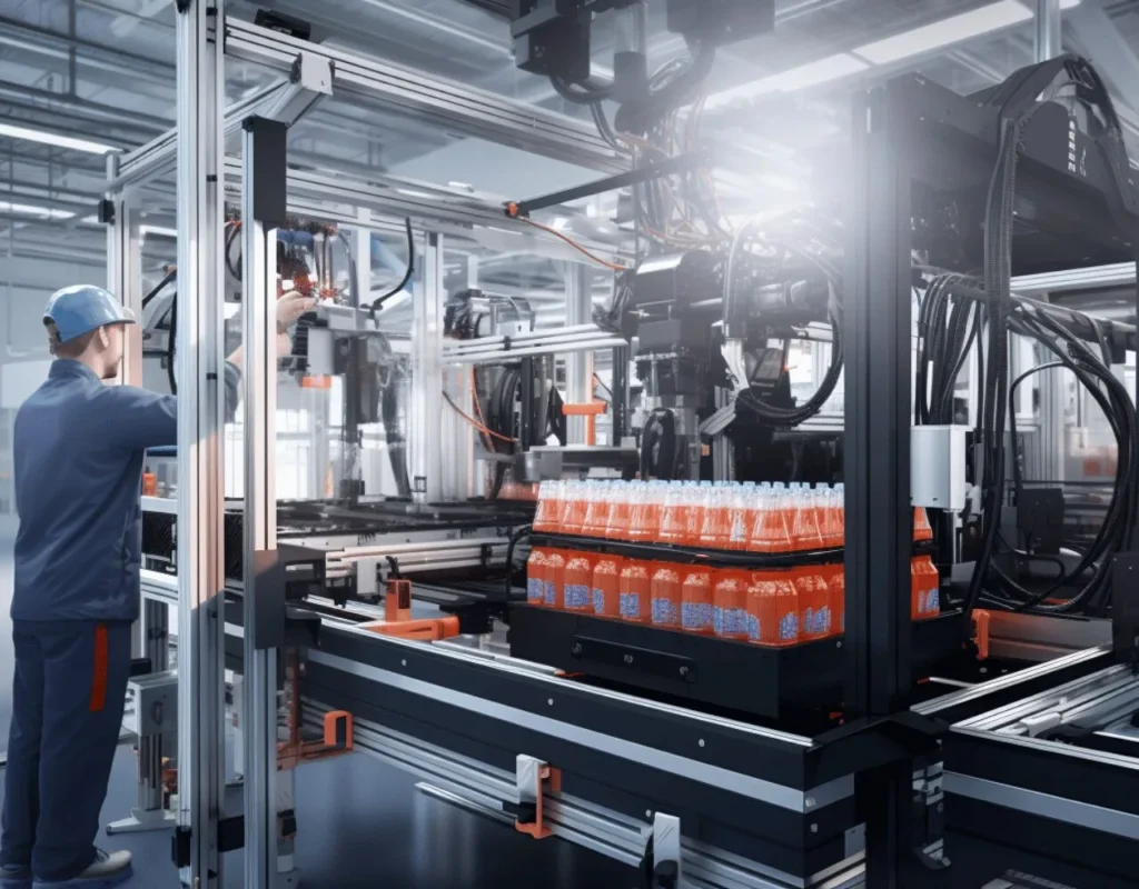 Packaging
 Railway
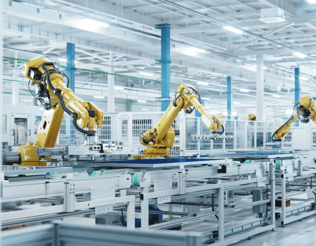 Robotics & Automation
 Special Vehicles
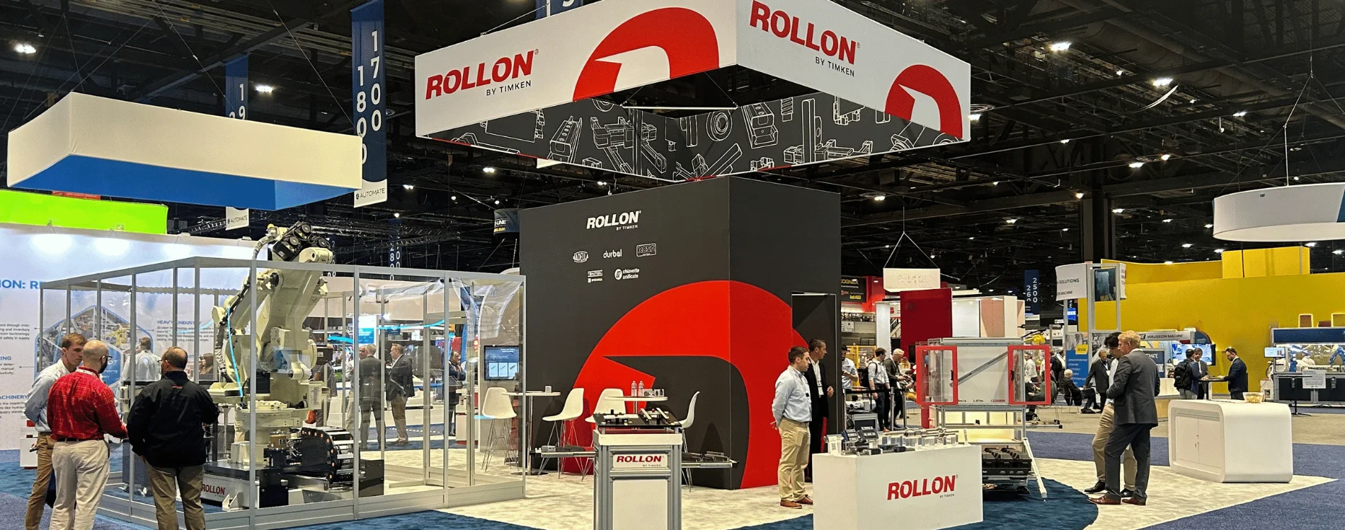


The linear actuator is one of the most fundamental components in industrial automation, providing the controlled linear displacement that underpins everything from precision assembly machinery to heavy-duty material handling systems. Despite the apparent simplicity of the concept, converting energy into straight-line motion, the engineering decisions involved in selecting the correct linear actuator for a given application are consequential and multifaceted.
The wrong choice can mean inadequate precision, insufficient load capacity, excessive maintenance demands, or a service life that falls well short of the application’s requirements.
What is a linear actuator? Definition and working principle
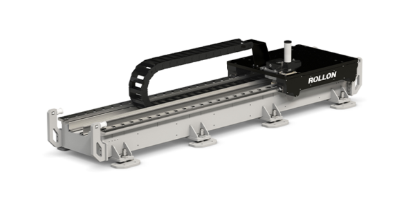
A linear actuator is a device that generates motion in a straight line, as opposed to the rotary motion produced by a conventional motor. In industrial applications, linear actuators are used wherever a load, tool, or end effector must be moved precisely from one position to another along a linear path. The actuator integrates a guidance system, typically a profiled rail and rolling element carriage, with a drive mechanism that converts an energy source into the required linear force and displacement. The combination of these elements in a single unit simplifies system integration and ensures that the structural, kinematic, and dynamic properties of the axis are designed to work together.
The performance characteristics of a linear actuator are defined by its load capacity, stroke length, positional repeatability, maximum speed, and the nature of its drive and guidance components. These parameters are interdependent, a heavy duty linear actuator designed for high static load capacity will typically have a larger, more rigid structure that limits achievable speed, whilst a high-speed belt-driven actuator will sacrifice some stiffness under load in exchange for dynamic performance. Understanding these trade-offs is essential for specifying the correct linear actuator for a given application.
Converting rotary motion to linear motion
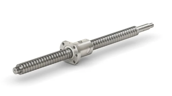
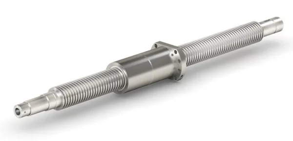
The majority of industrial linear actuators convert rotary input into linear output using one of several transmission mechanisms. In electric actuators, the most common conversion methods are the ball screw, which converts rotary torque into precise linear force with high efficiency, and the toothed belt, which transmits motion across longer strokes at higher speeds.
Another widespread solution is the rack and pinion, a mechanism in which a rotating pinion gear drives a linear rack; this configuration provides high thrust, excellent rigidity, and is well‑suited for long strokes and harsh industrial environments.
Belt-driven vs ball-screw vs rack-and-pinion electric actuators
Within the electric linear actuator category, the choice between belt‑driven, ball‑screw, and rack‑and‑pinion configurations is one of the most consequential design decisions an automation engineer will make.
Belt-driven linear actuators use a toothed belt looped around drive and idler pulleys to translate rotary motor motion into linear carriage displacement. This configuration achieves high axis speeds, typically several metres per second, across long strokes, with relatively low noise and vibration. The compliance inherent in the belt means that positional accuracy under varying axial load is slightly lower than a ball-screw equivalent, but for the majority of high-speed transfer and pick and place applications, this difference is within the acceptable tolerance window.
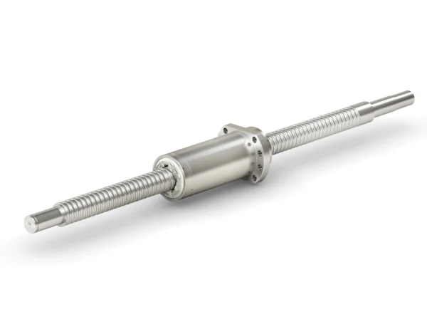
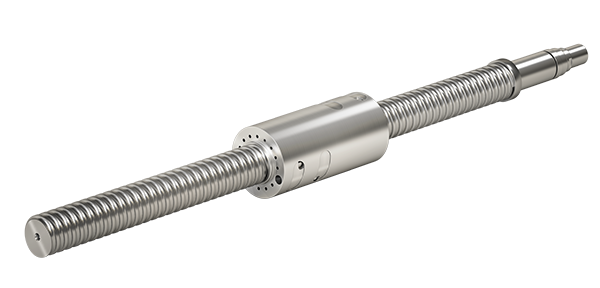
Ball-screw linear actuators convert rotary motion to linear displacement through a threaded screw and recirculating ball nut assembly. This mechanism provides superior positional stiffness and repeatability under axial load, making it the preferred drive for precision machining axes, measurement systems, and any application where the electric linear actuator must maintain its positional accuracy whilst resisting significant process forces.
The ball screw linear actuator is typically limited to shorter strokes than belt-driven equivalents beyond approximately two metres, screw whip under high-speed rotation becomes a design constraint and achieves lower maximum speeds, but within its operating envelope it delivers a level of precision that belt drives cannot match.
Rack-and-pinion linear actuators employ a rotating pinion gear that engages a linear rack to convert rotary input into linear motion. This architecture combines high thrust capacity with excellent rigidity and is particularly suited for long‑stroke applications where precision and robustness must be maintained without the stretch or compliance typical of belt systems. Unlike ball screws, rack‑and‑pinion drives do not suffer from screw whip at extended lengths, enabling high speeds across multi‑metre travel ranges while preserving stiffness under varying loads. Although their positional accuracy and repeatability are generally below those of high‑precision ball screws, rack‑and‑pinion actuators offer a balanced compromise of speed, load capacity, and mechanical durability, making them a strong choice for demanding industrial automation tasks, heavy‑duty gantries, and harsh environments.
Key selection criteria: load, speed, stroke and precision
Specifying the correct linear actuator for an industrial application requires systematic evaluation of four primary parameters. Load capacity covers both the static weight of the payload and the dynamic forces generated during acceleration and deceleration, a heavy duty linear actuator must be rated for the peak dynamic load, not simply the static weight, to avoid premature wear of the rolling element guidance and drive components. Speed requirements must be defined in terms of the full motion profile (acceleration, constant velocity, and deceleration phases) rather than peak velocity alone, as the acceleration phase generates the highest forces on the actuator structure.
Stroke length determines the physical size of the linear actuator and constrains the choice of drive mechanism, as described in the comparison above. Precision, expressed as positional repeatability, defines the tolerance within which the actuator must reach its target positions and is the parameter most directly affected by drive mechanism choice, preload, and the quality of the guiding components.
Matching actuator specifications to your application
A disciplined approach to linear actuator selection begins with a complete specification of the application’s dynamic load envelope, required positional accuracy, duty cycle, stroke, and environmental conditions. With these parameters defined, the choice of drive mechanism and guidance system follows logically. For applications combining long stroke with moderate precision and high speed, a belt-driven electric linear actuator will typically be the most appropriate choice. For short-stroke, high-precision tasks under significant axial load, a ball screw actuator is usually preferred. For the heaviest industrial loads, a rack and pinion linear actuator with carriages and a reinforced structural profile provides the required load rating with adequate safety margin.
Rollon linear actuators: high-performance solutions for UK industry
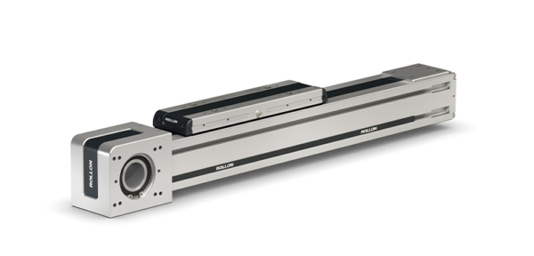
Rollon’s range of Linear Actuators is designed to cover the full spectrum of industrial automation requirements, from compact high-speed belt-driven units for packaging and assembly machinery to robust heavy-duty configurations for material handling and machine tool applications. Each product family within the range is engineered with precisely manufactured profiles, optimised preload configurations, components and materials appropriate for the intended operating environment, contributing to the reliability of the linear actuator over its specified service life without excessive maintenance intervention.
The product line includes solutions with belt, ball screw, and rack‑and‑pinion drives, available with recirculating ball guides or roller guides to meet different load, stiffness, and environmental requirements.
FAQs
What is a linear actuator and how does it work?
A linear actuator is a device that converts an energy input into controlled straight-line motion, moving a load along a defined linear path. The working principle depends on the actuator type: an electric linear actuator uses a motor combined with a ball screw or belt drive to convert rotary motion to linear displacement, whilst a pneumatic linear actuator uses compressed air acting on a piston to generate linear force directly. Industrial linear actuators integrate the drive mechanism with a guidance system to ensure accurate, repeatable motion under the dynamic loads of the application.
What are the main types of electric linear actuators?
The three principal types of electric linear actuators are belt‑driven, ball‑screw, and rack‑and‑pinion systems. Belt‑driven actuators are designed for high‑speed motion over long stroke lengths, making them ideal for dynamic handling, transfer, and pick‑and‑place tasks. Ball‑screw actuators provide superior positional stiffness and repeatability under axial load, delivering the precision required for measurement systems, controlled assembly processes, and any application that demands highly accurate, repeatable linear positioning. Rack‑and‑pinion actuators combine high load capacity with excellent rigidity and are particularly suited to long‑travel applications where belt compliance or screw whip would be limiting factors. Together, these three drive technologies cover the full spectrum of performance requirements in electric linear motion, from speed and precision to robustness over extended distances
What linear actuator specifications matter most for industrial automation?
For industrial automation applications, the four most critical linear actuator specifications are dynamic load capacity, positional repeatability, maximum speed, and stroke length. Dynamic load capacity must account for acceleration forces, not just static payload weight, particularly in high-cycle applications where peak dynamic loads may be several times the static load. Positional repeatability governs how consistently the linear actuator reaches its target positions, with demanding applications such as assembly and dispensing requiring repeatability in the range of ±0.05 mm or better. For heavy duty linear actuator applications, the moment load rating of the rolling element carriage is an equally important parameter, as eccentric loading from offset payloads places significant bending moments on the guidance system.